INTER-METH based on INTER-IoT
In this Section, the INTER-METH instantiation process is shown. In particular, the Abstract phases of Analysis, Design, Implementation, Deployment, Testing and Maintenance, are customized with the aim of showing how the integration process between two heterogeneous IoT platforms/systems can be concretely carried out by exploiting the INTER-METH guidelines and INTER-IoT products, in particular, INTER-LAYER and INTER-FW. For each phase of the instantiated process, an overall description is reported along with the list of performed activities and obtained work products.
Phase 1: Analysis
Description: Given two or more IoT platforms/systems to be integrated, the integration requirements need to be elicited. On the basis of the elicited requirements, the INTER-IoT-based design of the IoT platforms integration could be then carried out.
Objectives: To provide a model of the requirements for the integration of IoT platforms/systems.
Actors: The actors are:
(a) The developer of the integration (aka Integrator), who carries out the integration interconnection of heterogeneous IoT platforms; the Integrator is an active performer.
(b) The platform Owner, who will obtain the integrated platform;
(c) The involved Platforms to be integrated.
Expected results: INTER-GOM (Goal-Oriented Model), a final model that will represent the formal requirements models.
Main execution:
- On the basis of the Integration Goals, each platform is analysed according to the INTER-IoT Reference Architecture (see D4.1/D4.2) and the requirements of integration among the layers of the platforms to be integrated are defined according to iterative tasks enclosed in activities.
- According to the Step 1, the requirements of integration among the layers of the platforms to be integrated are defined according to iterative tasks enclosed in activities.
Activities
The analysis phase of the concrete instantiation consists of three main tasks that are performed by the Integrator (see Figure 1.3) according to the workflow depicted in Figure 1.4.
IoT Platforms Analysis: receives two heterogeneous IoT systems inputs: A and B. According to the INTER-IoT Reference Architecture, they are analyzed, thus producing the Analyzed Platforms Document. This step allows heterogeneous IoT platforms/systems with even notably different architectures to be compared by means of a common set of architectural solutions and building blocks. In particular, the INTER-IoT Reference Architecture is based on IoT-A (see Deliverable D4.2), which represents the most known and adopted IoT reference architecture. Aiming at the creation of an architectural reference model along with the definition of an initial set of key building blocks for enabling the emerging IoT, the IoT-A reference architecture provides views and perspectives on different architectural aspects that are of concern to stakeholders of the IoT. IoT-A functional architecture consists in the following Functional Groups: Device (technical artefact meant to provide an interface between the digital and the physical worlds), Communication (with regards to the plethora of communication technologies that the IoT ARM needs to support, the need for a Communication FG is identified), Service Organization and IoT Process Management (requirements expressed by stakeholders regarding the possibility to build services and applications on top of the IoT are covered by the IoT Process Management and Service Organisation FGs), Virtual Entity IoT Service and Application (derived from the main abstractions identified in the Domain Model), Security (to address consistently the concern expressed about IoT Trust, Security and Privacy, the need for a Security transversal FG is identified) and Management (to address consistently the concern expressed about IoT Trust, Security and Privacy).
The INTER-IoT Reference Architecture based on IoT-A is portrayed in Figure 1.1.
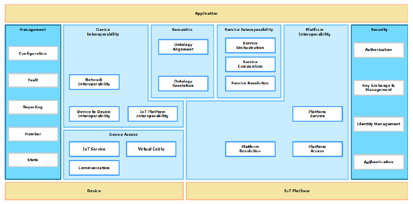
Figure 1.1: INTER-IoT Reference Architecture schema.
The INTER-IoT Reference Architecture contains 11 Functional Groups (FGs): the Application FG, the Device FG and the IoT Platform FG are out-of-scope of the INTER-IoT Reference Architecture, because they represent external groups that are going to be interoperated through the INTER-IoT and have been represented in yellow color. The five longitudinal FGs (Device Interoperability, Semantics, Service Interoperability, Platform Interoperability, Device Access) are represented in light blue color. The Management FG and the Security FG are transversal Functionality Groups and are shown in dark blue color. These transversal groups provide functionalities that are required by any of the longitudinal groups. In particular:
- Service Interoperability FG: supports the Application & Service to Application & Service (AS2AS) interoperability through the definition and execution of new compound services that make use of already existing services in the underlying IoT Platforms. Its goal is to use services from different IoT and create new services based on them.
- Semantics FG: addresses the challenges related to semantic interoperability of IoT Platforms. It provides support for the other FGs dealing with interoperability about IoT: The Service Interoperability FG, the Platform Interoperability FG and the Device Interoperability FG.
- Platform Interoperability FG: interacts with the different IoT Platforms to be interconnected. It is the responsible for accessing the IoT Platforms, not for implementing any of the features that the IoT Platforms provide.
- Device Interoperability FG: addresses the challenges of making legacy devices and non-real IoT Platform interoperable with other IoT Platforms and systems.
- Device Access FG: is responsible for offering a common interface to services and virtual entities that represent and expose functionality of physical devices. It abstracts all the necessary functions for managing the devices and interacting with them.
- Management FG: considers all the functionalities needed to rule the interoperability among different IoT Platforms. It is responsible for initializing, monitoring and modifying the operation of the interoperability among IoT Platforms.
-
Security FG: is responsible for ensuring all the security aspects involved in the interoperability of IoT Platforms.
-
Integration Layer Identification: receives in input the Analyzed Platform Document and a set of Integration Goals. In output, produces the document Categories of Integration (CoI), a set of INTER-IoT integration layers and of the cross-layering.
The INTER-LAYER (INTER-IoT layered-oriented approach) architecture (see WP4) is reported in Figure 1.2.
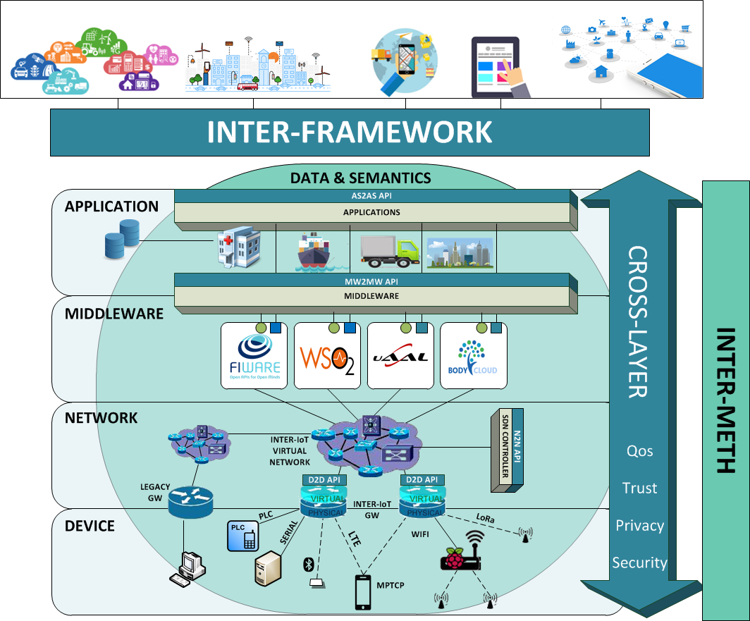
Figure 1.2: The INTER-LAYER approach schema.
As extensively reported, INTER-IoT presents a layer-oriented solution for interoperability, to provide interoperability at any layer and across layers among different IoT systems and platforms. This layer-oriented solution is achieved through INTER-LAYER and includes several interoperability solutions dedicated to specific layers. The different layers are:
- Device: allows the seamless inclusion of novel IoT devices and their interoperation with already existing ones.
- Network(ing): aims to provide seamless support for smart objects mobility and information routing.
- Middleware: enables seamless resource discovery and management system for the IoT devices in heterogeneous IoT platforms.
- Application & Services: enables the use of heterogeneous services among different IoT platforms.
- Semantics & Data: allows a common interpretation of data and information among different IoT systems and heterogeneous data sources, achieving semantic interoperability.
-
CROSS-LAYER: covers and guarantees non-functional aspects that must be present across all layers: trust, security, privacy, and quality of service (QoS).
-
INTER-GOM Production: receives the Analyzed Platform Document, a set of High-Level Integration Goals and the Categories of Integration, and produces, according to the GOM Meta Model, the INTER-GOM (Goal-Oriented Model) as output. To obtain the final model that will represent the formal requirements model and will drive the INTER-IoT-based Design Phase, the INTER-GOM Production Task can be iterated one or more time.
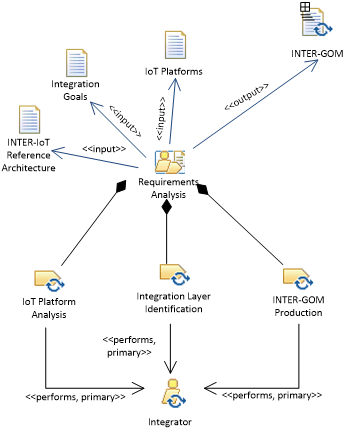
Figure 1.3: The INTER-IoT-based Analysis phase described in terms of activities, roles, and work products
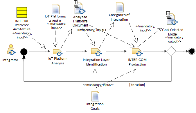
Figure 1.4: The workflow of tasks of the INTER-IoT-based Requirement Analysis activity
Work Products
The final output work-product is the INTER-GOM, a final model (compliant to the Metamodel reported in Figure 1.5) that will represent the formal requirements model and will drive the INTER-IoT-based Design Phase.
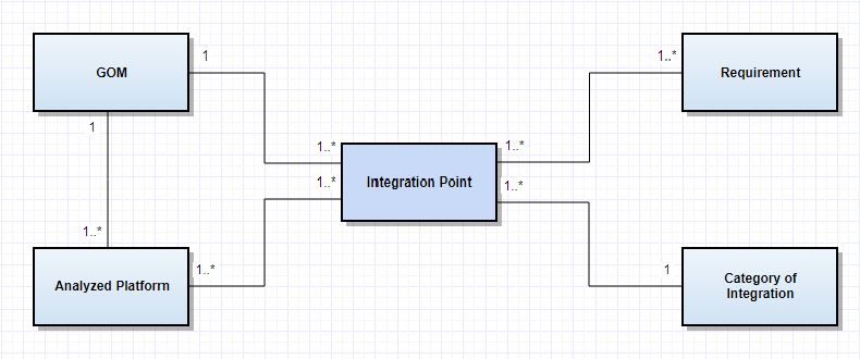
Figure 1.5: The Metamodel of INTER-GOM
The Metamodel of INTER-GOM is reported in Figure 1.5 and is composed of four main elements. In particular:
- Analyzed Platform Document: comparing the platforms using a homogeneous and shared architectural representation (see above), allows to identify the integration points between the platforms.
- Integration Point: Tropos defines the concept of Refinement. A refinement of an Element (e.g., a Goal) is a conjunction of the sub-elements that are necessary to achieve it. We will call these points of refinement, Integration Points (see Figure 1.6). They put together parts of the platforms according to the layer-based architectural model. It is possible to define a general and a specific level of refinement, according to INTER-IoT Reference Architecture: the first level identifies the Functional Groups, the second level the Functional Components (see Figure 1.1).
For each Integration Point, there are one or more:
- - Requirement: represents desired states we want the Integration Point to achieve. They are progressively refined into intermediate goals, until the process produces actionable goals (tasks) that need no further decomposition and can be executed. One or more requirements can be associated to a single Integration Point. - Category of Integration (CoI): identifies the level of interoperability in a set of INTER-IoT integration layers and of the cross-layering.
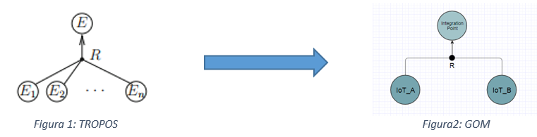
Figure 1.6: Refinement Process schemes in TROPOS and in INTER-METH
According to the Analyzed Platform Document_s and a set of _Integration Points, the GOM is defined, following an iterative procedure as shown in the activity diagram in Figure 1.7. The execution of the activity diagram is as follows:
- The first activity is the Integration Point Identification. According to the transition conditions, the activity flow loops according to the need of choosing other integration points, otherwise it moves to the next activity: Integration Point (IP) Requirement Identification;
- The second activity identifies one or more IP requirements before proceeding to the final GOM generation;
- Finally, if no further IP requirement has to be identified, the GOM document is generated and the process ends.
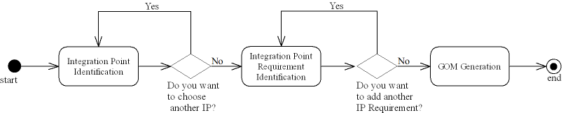
Figure 1.7: The UML Activity Diagram of INTER-GOM Production
Phase 2: Design
Description: Given two or more IoT platforms/systems whose formal integration requirements are reported in INTER-GOM model (generated as output of INTER-IoT-based Analysis Phase), a set of INTER-IoT DESIGN PATTERNS have to be produced. On the basis of the INTER-IoT DESIGN PATTERNS (documented in D5.1), the implementation of the IoT platforms integration could then be carried out by INSTANTIATION.
Objectives: To define the INTER-IoT DESIGN PATTERNS for the integration of IoT platforms/systems
Actors: The actors are:
(a) the developer of the integration (aka Integrator), who carries out the integration interconnection of heterogeneous IoT platforms; the Integrator is an active performer.
(b) the platform Owner, who will obtain the integrated platform;
(c) the involved Platforms to be integrated.
Expected results: Set of INSTANTIATED INTER-IoT DESIGN PATTERNS for the integration of the identified IoT platforms/systems.
Main execution:
- For each layer, on the basis of the elicited requirements reported in the INTER-GOM, an initial INTER-IoT DESIGN PATTERN is produced.
- Each INTER-IoT DESIGN PATTERN produced in Step 1 is iteratively refined.
- A global integration design (including the cross-layer) is defined on the basis of the outcome of Step 2 (and iteratively refined, if needed).
Activities
The Integration Design activity, which is the only main activity of the INTER-IoT-based Design phase, is subdivided into two main tasks that are performed by the Integrator (see Figure 1.8 and Table 1.1) according to the workflow depicted in Figure 1.9:
- INTER-IoT Layer Integration Design Specification: on the basis of the INTER-GOM and Analyzed Platforms Document, for each INTER-IoT Layer (Device, Network, Middleware, Application, Service, Data & Semantics) a layer integration specification is iteratively defined by exploiting the INTER-LAYER product (D2D, N2N, MW2MW, AS2AS, DS2DS). Such task will produce six INSTANTIATED INTER-IoT Design Patterns, one for each INTER-IoT layer.
- INTER-IoT Full Integration Design Specification: On the basis of the six INSTANTIATED INTER-IoT Design Patterns from the previous task, a full-fledged specification is iteratively produced by incorporating the CROSS-LAYER and INTER-FW INTER-IoT Design Patterns.
In particular, INTER-IoT PATTERNS (or INTER-PATTERNS) are design patterns directly corresponding to the integration solutions already achieved in the WP3 (particularly, according to INTER-LAYER) and WP4 (particularly, according to the INTER-FW for contextualize solutions in different application domains, e.g. m-Health, Transportation and Logistics) and they aim at furnishing well-formalized domain-specific guidelines. Note that WP5 depends on WP3 and WP4 outcomes, while WP3 and WP4 are independent from WP5. The defined set of INTER-PATTERNS comprises the element listed in Table 1.2, where is reported also their related INTER-IoT layer and inspiring Pattern Catalog (if any).
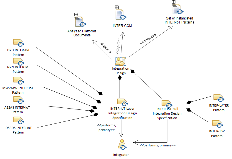
Figure 1.8: The INTER-IoT-based Design phase described in terms of activities, roles, and work products
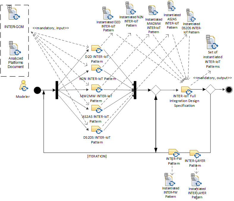
Figure 1.9: The workflow of tasks of the INTER-IoT-based Design Integration activity
Table 1.1: INTER-IoT Design Patterns, their related INTER-IoT layer and inspiring Pattern Catalogue
| Layer | Name of INTER-IoT PATTERN | Inspiring PATTERN CATALOG |
|---|---|---|
| D2D | INTER-IoT Gateway Event Subscription. | IoT Patterns, Enterprise Integration Patterns, Agent Design Patterns. |
| D2D | D2D REST Request/Response. | Reactive Patterns, IoT Patterns, Integration Patterns. |
| N2N | INTER-IoT Orchestration of SDN Network Elements. | |
| MW2MW | INTER-MW Simple Component Pattern. | Reactive Patterns. |
| MW2MW | INTER-MW Message Broker. | Integration Patterns, IoT Patterns. |
| MW2MW | INTER-MW Self-contained Message. | Reactive Patterns, SOA Patterns. |
| MW2MW | INTER-MW Message Translator. | Integration Patterns. |
| AS2AS | AS2AS Flow Based Service Composition. | |
| AS2AS | INTER-AS2AS Service Orchestration. | Service Orchestration. |
| AS2AS | AS2AS Discovery of IoT Services. | IoT Patterns, SOA Patterns. |
| DS2DS | Alignment-based Translation Pattern. | Integration Patterns, Agent Design Patterns. |
| DS2DS | Translation with central ontology. | Integration Patterns, Agent Design Patterns. |
| CROSS | INTER-IoT SSL CROSS-Layer secure access | Security Patterns, IoT Patterns. |
| INTER-FW | Configuration delegation pattern. | Object-oriented Patterns. |
| INTER-FW | API facade. | |
| INTER-HEALTH | INTER-Health Pilot Integration. | Enterprise Integration Patterns. |
| INTER-HEALTH | Integrated deployment in security-constrained environments. | Security Patterns. |
| INTER-LogP | Geofencing pattern. |
As it could be noted, three patterns catalogs have inspired the INTER-PATTERNS: IoT Patterns (which is obvious choice, because it describes the IoT solutions), Reactive Patterns (mainly because of its responsive and simple solutions) and Integration Patterns Catalog (mainly because of its effective and common message solutions). Regardless to their functionality, the template-based approach of describing all the INTER-IoT PATTERNS comprises twelve properties (as extensively reported in D5.1) Pattern name, Identifier, Inspired by, Related patterns, Intent, Problem & Solution, Applicability, UML representation, Implementation, Known uses, Identified by, Registration date.
Work Products
The work product of this phase is a set of INSTANTIATED INTER-IoT Design Patterns to be exploited for driving the implementation phase. Each INSTANTIATED INTER-IoT Design Pattern is described in a xml file according to the template previously reported, containing, among others, the UML representation attribute that contains an URL to graphical resources (formal diagrams, e.g., UML diagram, generated through an external tool).
Phase 3: Implementation
Description: Given two or more IoT platforms/systems whose integration has been designed according to the INSTANTIATED INTER-IoT Design Patterns, the Inter-IoT based integration implementation has to be performed.
Objectives: To concretely integrate/interconnect the considered IoT platforms/systems.
Actors: The actors are:
(a) the developer of the integration (aka Integrator), who carries out the integration interconnection of heterogeneous IoT platforms; the Integrator is an active performer.
(b) the platform Owner, who will obtain the integrated platform;
(c) the involved Platforms to be integrated.
Expected results: The Inter-IoT based integrated IoT platform/system.
Main execution:
- The INSTANTIATED INTER-IoT Design Patterns produced in the INTER-IoT based Design phase are actually implemented according to successive refinement steps.
Activities
The INTER-IoT based Integration Implementation activity, which is the only main activity of the Implementation phase, includes one main task that is iteratively performed by the Integrator (see Figure 1.10) according to the workflow depicted in Figure 1.11:
- INTER-IoT based__Systems Integration: on the basis of the INSTANTIATED INTER-IoT Design Patterns, the heterogeneous IoT platforms/systems are integrated by the Integrator in an iterative activity aimed at obtaining the final integrated platform. At this step, we can: (i) configure the components of the Integrated Platform by means of the INTER-FW; (ii) extend the components of the Integrated Platform (e.g., a new functionality enabled by the integration needs to be implemented); and (iii) to implement, in terms of software bridges connected to INTER-LAYER, the INTER-IoT based INTER-LAYER design patterns. As results of each these three sub-activities, the Integration Design Specifications are updated.
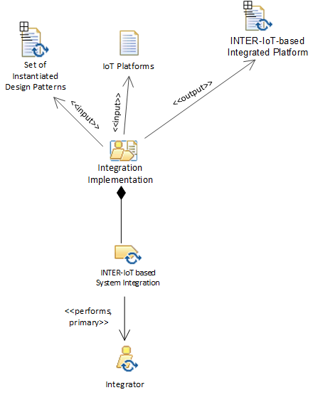
Figure 1.10: The INTER-IoT-based Implementation phase described in terms of activities, roles, and work products
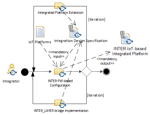
Figure 1.11: The workflow of tasks of the INTER-IoT-based Integration Implementation activity
Work Products
The final output work-product is the INTER-IoT-based Integrated Platform. If needed, an ontology alignment may be performed at this step through the IPSM tool, which will be presented in detail in D5.3 (INTER-CASE Tool). Such process consists in finding of correspondences between two or more ontologies. The result of this process is an alignment of a set of correspondences between entities (atomic alignment) or groups of entities and sub-structures (complex alignment) from different ontologies. A correspondence can be either a predicate about similarity, called a matching, or a logical axiom mapping.
At this point, the heterogeneous IoT platforms/systems are integrated according to the INTER-IoT approach, thus obtaining interoperability among them and allow implementation and deployment of IoT applications on top of them.
Figure 1.12 reports the relationships that are established among the different phases and work products.
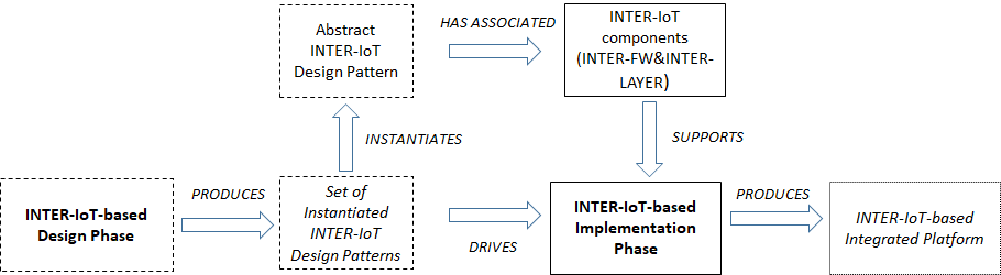
Figure 1.12: Relationships among the different phases (in bold) and work products (in italic)
Phase 4: Deployment
Description: Given two or more IoT platforms/systems, whose integration has been implemented according to the Implementation phase, the deployment of the integrated platform has to be performed.
Objectives: To deploy the integrated IoT platforms/systems.
Actors: The actors are:
(a) the developer of the integration (aka Integrator), who carries out the integration interconnection of heterogeneous IoT platforms; the Integrator is an active performer.
(b) the platform Owner, who will obtain the integrated platform; the Owner is an active performer.
(c) the involved Platforms to be integrated.
Expected results: The deployed IoT platform/system.
Main execution:
- The Integrated Platform is deployed according to deployment goals and requirements. In particular, the INTER-FW web framework is the entry point to the INTER-IoT Configuration and Management Framework (CMF), one of the three main software results of WP4, together with INTER-API and the Software Development Framework. The use of INTER-FW CMF (from now on, INTER-FW for shortness) is baseline for the IoT Platforms deployment phase in the scope of INTER-METH. Thus, the INTER-IoT-based Deployment Phase of INTER-METH is strongly dependent on INTER-FW. The first version of the INTER-FW has eight sections (or modules), from which six of them are directly involved in the deployment of interoperable IoT Platforms. INTER-IoT treats the five defined interoperability layers in separate concerns, so five of these modules correspond 1-to-1 to these concerns. The sixth module is related to AAA (Accountability, Authorization and Authentication).
Activities
The INTER-IoT based Deployment activity, which is the only main activity of the Deployment phase, comprises six main tasks that are performed by the Integrator/Configurer (see Figure 1.13) according to the workflow depicted in Figure 1.14 (in particular, the activities are strongly connected to the UI functionalities of the different modules based on INTER-FW and so will be described):
-
Platform Configuration: this task (connected to the Platforms module) deals with the deployment of complete IoT Platforms for interoperating them towards rich applications. Although the technical focus of this module is the deployment of interoperable middlewares of platforms, the whole content (i.e., the platform) has been assumed to the concept of 'middleware' since the IoT platforms are univocally bound to the concept of platform (there are few or none platforms without a middleware, while there are middlewares not linked with specific platforms, though). To instantiate and deploy an IoT Platform Middleware in the INTER-FW to enable middleware interoperability, the following steps are followed:
-
A bridge of the platform to interoperate must be available. INTER-IoT provides a series of reference bridges. If the platform is not in the list of reference implementations, this must be done following the "developing new bridges" instructions that will be publicly available by the end of the project in the project site in GitHub. These instructions will extensively use the Software Development Framework of the project.
-
Deploy the platform following the deployment instructions of the platform vendor/developer. The platform must be reachable in a public endpoint (via DNS or IP).
-
Access the Platforms module (through its GUI)
-
Add a new Platform
-
Provide the following information (through filling in a given form), according to the following fields:
4.1. Name: the name of the Platform (arbitrary)
4.2. Type: the type of Platform selected from the reference implementations in INTER-IoT
4.3. Bridge: the bridge applicable to the platform. One platform can be interfaced through different bridges (e.g. different versions or different natively unavailable method implementations).
4.4. Security: the security approach used to connect with the Platform, chosen from a list.
4.5. Owner: the user that allows the property of the data and the responsibility of them. It must be a user already registered in INTER-FW.
4.6. URL and port: the endpoint to reach the public instance of the Platform. The GUI allows checking whether or not the introduced endpoint is reachable from the location where INTER-FW is deployed.
- Save the all the information (i.e. the form). If all the fields are filled properly, the Platform should now be available in the INTER-FW environment. The platform will appear in a list in the main section of the Platforms module.
To explore the list of devices registered in a platform, its entry can be properly selected in the list of platforms. This view contains two tabs: a) the first entry "Platform" shows the details of the platform; b) the second entry "Entities" has a list of devices connected to the platform. New devices can be registered (e.g. by using the "Add" button). Entities can be explored or deleted from the list.
-
Gateway Configuration: this task (connected to the Gateways module) focuses on the device to device interoperability, addressed in the scope of INTER-IoT in the D2D Layer through the "Gateway Event Subscription" and "REST Request/Response" patterns (as described in D5.1). The steps to add a new gateway are:
-
A gateway with the gateway software of INTER-IoT must be available. The hardware must be compatible with the INTER-IoT Gateway software. The compatibility list will be published in the INTER-IoT Gateway development site in GitHub.
-
Select the Gateways module in the INTER-FW
-
Add a new Gateway
-
Providing the following information (by filling in the GUI form), containing the following fields:
4.1. Name: the given name of the physical Gateway
4.2. URL and port: the endpoint to reach the public instance of the Gateway. The form allows checking if the introduced endpoint is reachable from the location where INTER-FW is deployed.
4.3. Owner: the user that allows the property of the data and the responsibility of them. It must be a user already registered in INTER-FW.
- Save the provided information. Once the Gateway is created, if the data are correct and the gateway is reachable, the gateway will appear in the list of physical gateways. A virtual instance of the gateway is automatically created following the pattern "Digital Twin".
To explore the list of devices registered in a gateway, select the list of registered gateways in its entry. This view contains three entries: the first "Gateway" shows the details of the gateway; the second "Physical" has a list of devices connected to the platform; the third, "Api" links to the API of the layer interoperability implementation. Entities can be explored or deleted from the list.
-
Networking Configuration: in this task (connected to the Networking module), the network interoperability, achieved via network virtualization and "Virtual Network Orchestration" pattern is configured and managed, supporting the needs of the N2N layer of INTER-IoT in terms of implementation and deployment. The module of Network is divided in three subsections (or views):
-
Topology: an informative view aimed to show the emulated network topology.
-
Statistics: It has two functions: one to manage (read, create, modify, remove) network ports and another to manage network flows.
-
QoS: where the statistics of the different network devices and segments are displayed. This view offers the possibility to set up new queues and new network rules and related metrics. All these elements can be managed from their respective lists, allowing editing or removing.
-
Application Services Configuration: this task (connected to the Application Services module) includes a graphic tool for service orchestration, the underlying interoperability mechanism for AS2AS Layer (see D3.2). This is one of the less intrusive views in the INTER-FW, since the implementation tool, the open source project "node-red" has a powerful user interface which allows this service orchestration from a visual perspective. The initial view in INTER-FW of the Services section shows a list of already existing workflows.
-
To create a new workflow, it must be clicked the "Add" button, while existing ones can be modified by clicking their entry in the list or clicking the "Remove" button to delete them.
-
Adding a new node creates a new instance of the "node-red2 tool enhanced by INTER-IoT.
-
To set up a new workflow in the UI of the service orchestrator, components must be dragged and dropped to the canvas and connected via virtual wires.
-
Double clicking each component gives access to the configuration of the services.
-
To deploy new orchestrated services, the deploy button is to be clicked. If no error has been raised, the new workflow will start working immediately.
-
Semantics Configuration: in this task (connected to the Semantics module), all the configurable parameters and processes related to the semantics interoperability (all mechanism present in the DS2DS layer, see D3.2) are configured for the deployment of interoperable IoT platforms. The view contains five sections.
-
To add a new mediator instance, the IPSM (Inter Platform Semantic Mediator) Configuration tab needs to be selected and then a "Register IPSM instance" created, the URL and port of the instance where the IPSM instance to be deployed will be requested.
-
To create new IPSM alignments, a new alignment instance has to be created through "Add Alignment". A form asking for the possible combinations will be used. After filling the information, the new alignment will be created. The created alignments can be administered (modify, remove) from the same tab. The catalogue of available alignments is populated from the IPSM authoring tool, currently not available in the INTER-FW, which will be created in the context of the INTER-CASE tool (see T5.3).
-
To set up translation channels (to improve performance), "Add channel" functionality is used. Channels are managed from the same view.
-
To explore the available ontologies, "Ontology repository" tab can be selected. Ontologies can be added by using "Add Ontology".
-
User management Configuration: this task (connected to the User management module) contains configurations valid for all the previous modules (or sections); in particular, it configures and manages the users of the INTER-FW and the authorized access of them to the IoT resources connected in INTER-IoT. To add a new user, the following steps must be followed:
-
The current user must have administration permissions.
-
Select the "Users management" view. In this view, all the users of INTER-FW are listed. From this view they can be managed.
-
Add a new user.
-
Complete the form that contains the following fields:
3.1. Username: the INTER-FW login name for the application.
3.2. Password: the secret key for the user.
3.3. Name: the complete name of the user (optional)
3.4. Email: a valid email for the user. Communications will be issued to this address, so it must be valid. A verification mechanism (validator + two-step sign-up) checks that the user has introduced a valid email.
3.5. Company: The company of the user.
3.6. INTER-FW App role: The initial role. The role is applicable for the views that are initially rendered for the users.
-
Once the user is created, authorization to IoT artifacts connected through INTER-IoT can be granted/revoked by using the specific User entry and accessing the "Permissions" tab.
-
Specific policies for the user can be also assigned by using the Policies tab in the same view.
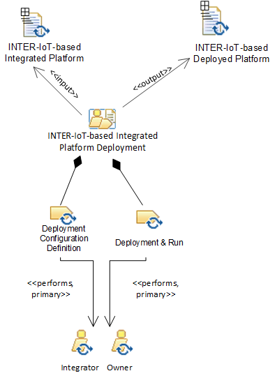
Figure 1.13: The INTER-IoT-based Deployment phase described in terms of activities, roles, and work products
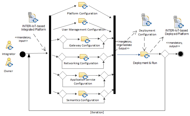
Figure 1.14: The workflow of tasks of the INTER-IoT-based Deployment activity
Work Products
The work product refers to the configured and deployment integrated IoT platform.
Phase 5: Testing
Description: Given two or more IoT platforms/systems, whose deployment has been carried out according to Deployment phase, the testing/validation has to be performed.
Objectives: To test the deployed integrated IoT platforms/systems.
Actors: The actors are:
(a) the developer of the integration (aka Integrator), who carries out the integration interconnection of heterogeneous IoT platforms; the Integrator is an active performer.
(b) the platform Owner, who will obtain the integrated platform; the Owner is an active performer.
(c) the involved Platforms to be integrated.
Expected results: The test results on the integrated and deployed IoT platform/system.
Main execution:
- The integrated and deployed platform is executed and validated through testing according to well-defined test cases. Acceptance testing is a test conducted to determine if the requirements of a specification are met [TE1]. In systems engineering it may involve black-box testing performed on a system, such as for example for software modules. International Software testing Qualifications Board (ISTQB), which is a software testing qualification certification organisation, defines acceptance as formal testing with respect to user needs, requirements, and business processes conducted to determine whether a system satisfies the acceptance criteria [TE2]. There can be many types of acceptance testing for a system, service or product. The acceptance test can be performed multiple times in the case of defect resolving or when test cases are not executed within a single test iteration. In INTER-IoT acceptance testing is performed in two phases: Factory Acceptance Testing (FAT) and Site Acceptance testing (SAT) [TE3]. Factory Acceptance Test (FAT) and Site Acceptance Test (SAT) are performed to test and evaluate the INTER-IoT-based integrated system implemented in the Implementation Phase and deployed in the Deployment Phase. During development, units and components are tested by the developers. After the integration of the tested and validated components in the system, the FAT will be executed in order to indicate if there are needs for improvements. After the successful execution, the system can be tested in the field and undergo the SAT.
Activities
The Testing activity, which is the only main activity of the INTER-IoT-based Testing phase, is subdivided into four main tasks that are performed by the Integrator/Tester (see Figure 1.15 and Table 1.1) according to the workflow depicted in Figure 1.16:
- Factory Acceptance Testing (FAT) Task. The FAT is performed to test and prove the system in a lab environment and tests if solution meets the specifications and if it is functional before it is deployed in the field. FAT tests can be performed by simulation or a functional test. FAT describes the system, test setup, tooling, test strategy, test activities and test results for the lab setup. During FAT testing the readiness of the system is shown to the customer. The readiness of the system is shown to the costumer, which can use the system in actual system setup for the first time. During the testing process, the operators and maintenance personal can get insight into the operated and maintained system. Minor irregularities can be detected which lead to minor changes in the INTER-IoT system before the system is deployed in the field.
- Site Acceptance Testing (SAT) Task. SAT takes place after integration at the customer site and tests if the solution has been correctly integrated into the customer's environment and meets all the requirements. The solutions are tested on: Integration, Performance, User acceptance, conformance to specifications. During the SAT testing process the actual deployed system is tested and proven. SAT process are similar like FAT process, except is describes and tests the system integrated in the customer systems. For each of the use-case/pilots a FAT and SAT testing will be performed.
- Test Environment__Task. The test environment is usually designed to be identical, or as close as possible, to the anticipated production environment. In order to test the IoT system/framework in "real world" as much as possible, representative test systems are needed where pilot test setups must be created and verified, which includes all facilities, hardware, software, firmware, procedures and/or documentation intended.
- Defect Reporting Task. For the defect reporting purpose, each integration project can be planned, tracked and reported in organized manner. During the integration testing new issues can be found, for which it has to be determined whether they are actually a defect or not. The defect has to be resolved by either developer, project manager or software architect. After the defect has been resolved, the solution will be integrated into the next release and tested during the next integration test.
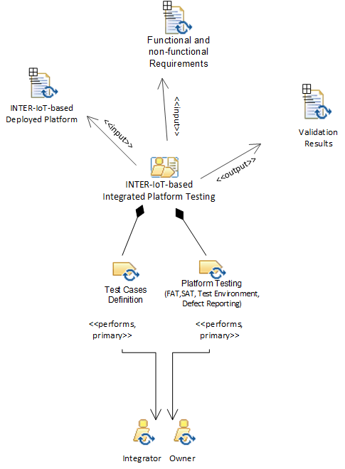
Figure 1.15: The INTER-IoT-based Testing phase described in terms of activities, roles, and work products
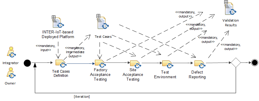
Figure 1.16: The workflow of tasks of the INTER-IoT-based Testing activity
Work Products
The FAT and SAT indices documents will constitute the output work products of such phase.
Phase 6: Maintenance
Description: Given an INTER-IoT-based integrated platform obtained from the integration of two or more IoT platforms/systems according to the previous phases, such platform needs to be maintained.
Objectives: To maintain and make evolve an integrated IoT platform.
Actors: The actors are:
(a) the developer of the integration (aka Integrator), who carries out the integration interconnection of heterogeneous IoT platforms; the Integrator is an active performer.
(b) the platform Owner, who will obtain the integrated platform; the Owner is an active performer.
(c) the involved Platforms to be integrated;
(d) the integrated Platform
Expected results: Continuous maintenance of the integrated IoT platform.
Main execution:
- Identification of a list of bugs and/or a list of evolution points at specific INTER-IoT layers and/or products.
- Correction of bugs and/or implementation of new functionalities (go back to the Analysis or Design phases).
Activities
The Integrated Platform Maintenance activity, which is the only main activity of the Maintenance phase, is subdivided into two main tasks that are performed by the Integrator and/or Owner (see Figure 1.17) according to the workflow depicted in Figure 1.18:
- Change Identification: this task aims at identifying bugs and/or evolution points of the integrated platform. Identification will be done at each layer (Device, Networking, Middleware, App Services, Data & Semantics) and cross-layer of the integrated platform (i.e. at INTER-LAYER) and at framework level (i.e. at INTER-FW).
- Change Implementation: actual implementation of the changes, i.e. bug fixing or analysis, design, implementation, deployment, and validation of new functionalities; the latter could imply to re-execute, totally or partially, the integration process.
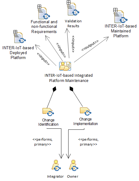
Figure 1.17: The Maintenance phase described in terms of activities, roles, and work products
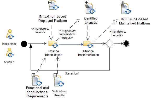
Figure 1.18: The workflow of tasks of the Integrated Platform Maintenance activity
Work Products
The final output work-product is the results of the maintenance activity, i.e. bug-fixing and/or evolution of the integrated platform.