Flowgraph Description
Initially, due to the limited processing power of the ARM CPU in the XC7Z035, GNU Radio blocks were used to implement the receiver and transmit sections on a separate PC linked via a network connection. Figure 3 and Figure 4 show the transmitter and receiver sections respectively, as implemented by GNU Radio. Further development to move the GNU Radio signal processing blocks onto the XC7Z035 FPGA was, unfortunately, not carried out due to limited time and resources.

Figure 2 GNU Radio Link Flowgraph (zmq_tuntap.grc)
ZeroMQ Flowgraph
In order to stop the flowgraphs from getting too large it was decided to keep the transmitter and receiver separate. However this then presented a problem when the data source was required to be a virtual network interface (TUN/TAP) as we want the same GNU Radio TUNTAP block to be accessible from both flowgraphs. One solution to this problem turned out to be ZeroMQ which is a high-performance asynchronous messaging library, and which is also supported by GNU radio.

Figure 3 GNU Radio Transmitter Flowgraph (tx_ofdm.grc)

Figure 4 GNU Radio Receiver Flowgraph (rx_ofdm.grc)
Transmitter Flowgraph
Header Generation and Packetization
Data to be transmitted over the radio link can be split into two types: (i) payload data from the ZeroMQ interface and (ii) the header information. The payload data contains the actual information to be transferred and the header data contains supervisory information about this payload, ensuring that it can be successfully received and interpreted at the destination. Due to the different tasks required by the two data types they need to be split into two divergent processing sections.
Both the header bits and payload bits need to be mapped to their required constellation points, given the modulation scheme being used. The channel quality will influence the modulation scheme used. However, the payload and header may not necessarily use the same symbol set and in this project the header is transmitted with BPSK modulation and the payload is transmitted with QPSK modulation.
A cyclic redundancy check (CRC) is independently appended to both the header and to the payload. This is used at the receiver for error detection. This adds redundancy to the transmitted data but is useful in giving a warning that data may not have been received correctly at the receiver.
OFDM Carrier allocator
The OFDM carrier allocator performs a number of functions including adding synchronisation words, pilot symbol insertion and sub-carrier allocation. More details on this block can be found in the GNU radio help.
Inverse Fast Fourier Transform (IFFT) and Cyclic Prefix Insertion
The IFFT block is used to translate from the frequency domain to the time domain. Bins within the IFFT block are loaded with constellation points which are mapped into frequency offset indexes. When the IFFT block is completely loaded, the Inverse FFT is computed, giving a set of complex time-domain samples representing the combined OFDM subcarrier waveform. This produces an OFDM symbol. The process is then repeated to create additional OFDM symbols for the remaining input data bits. The cyclic prefix is also appended to the time domain samples to combat the effect of multipath in the receiver.
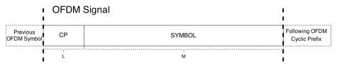
Figure 5 GNU Radio Receiver Flowgraph (rx_ofdm.grc)
Burst and Event Stream Blocks
During development it was discovered that, because we are running in a bursty FDD mode (i.e. the transmitter generates a finite burst of samples for each input packet), buffering in the FPGA fabric meant that spurious samples were generated between bursts. To overcome this problem the burst scheduler and event stream source blocks perform the function of producing a stream of zeros when there is no real data to transmit.
IIO Device Sink
This block sends data over the network to the SDR module which is running a IIO server in Linux user space. This then formats and forwards the data to the Analog Devices AD9361 radio transceiver IC.
Receiver Flowgraph
IIO Device Source
This receives data from the SDR module via the IIO server. It then formats and forwards the data in integer format which must then be converted to floating point for further processing
Synchronisation
When data is transmitted over the air the receiver needs to perform a synchronization procedure to obtain the start of the OFDM symbol. Schmidl and Cox proposed a synchronisation algorithm that bases the synchronisation on a special OFDM sync word. By performing some signal processing on the incoming signal is it possible to locate this sync word, perform fine carrier frequency offset correction and cyclic prefix removal.
FFT
Both the header and the payload require a Fast Fourier Transform (FFT) to convert the incoming signal from the time domain to the frequency domain.
Header Payload Demux
This block processes and buffers the incoming data steam so that the header and payload are demultiplexed. First the header is equalised and demodulated to find the length of the payload. Once this is accomplished the payload can then be processed. More details on this block can be found in the GNU radio help.
Channel Estimation
Distortions in the channel need to be accounted for at the receiver. The channel estimator tries to ‘compensate’ for these distortions by analysing known signals that have been sent through the channel. These ‘known’ signals are known as pilot symbols and are regularly sent from the transmitter so that the channel estimator can be updated.
OFDM frame equalizer
This block supplied by GNU radio is a decision-directed zero-forcing equalizer which applies the inverse of the channel frequency response to the received signal, to restore the signal after the channel.
Symbol De-mapping and Deallocation
Both the header bits and payload bits need to be ‘de-mapped’ and ‘de-allocated’ from their respective constellation points, given the modulation scheme being used. The channel quality will influence the modulation scheme used, and this is known at the receiver. However, the payload and header may not necessarily use the same symbol set. Each symbol, a complex-valued constellation point is converted back to the original bits that it represents: 2 bits for QAM, 4 bits for 16QAM, or 6 bits for 64QAM.
Check CRC
A cyclic redundancy check (CRC) is independently appended to both the header and to the payload. This is used at the receiver to check for error detection. If the CRC fails then the that block of data is not passed on.
ZMQ Push message
The ZMQ interface is used to access the TUNTAP virtual network port as described earlier.